,

API PLAN 23

  • Closed-loop cooling circulation:Seal chamber → pumping ring/circulation device → cooler → return to seal chamber, forming a self-contained loop.
  • Stable circulation driving force:During operation, circulation is mainly driven by the pumping ring/circulation sleeve, reducing temperature fluctuations in the seal chamber.
  • More efficient thermal isolation:Can be used with a close-clearance throat bushing to isolate the cooled seal chamber fluid from hotter pump fluid, reducing cooler duty.
  • Complete typical configuration:Includes cooler (commonly water-cooled or air-cooled), temperature indicator, high-point vent valve, and drain/vent connections.
  • Installation best practices:
  • Cooler should be installed close to the seal chamber.
  • A vent valve should be located at the highest point of the system.
  • Cooler location and piping routing should follow standards to avoid air binding or vapor lock.
    • Application purpose:Reduce seal face temperature without increasing pressure, limit flashing/vaporization at the seal faces, and improve service life and reliability.

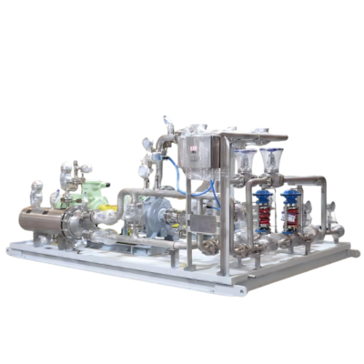
Plan 23 (API 682 process-side piping plan) is a closed-loop flushing and cooling system based on “internal recirculation within the seal chamber + cooler.” A circulation device inside the seal chamber (commonly a pumping ring or circulation sleeve) draws fluid from the seal chamber, sends it through a cooler for temperature reduction, and then returns it back to the seal chamber. This provides a lower and more stable operating temperature for the seal faces.

This arrangement reduces seal face temperature without additional pressurization, suppresses flashing/vaporization, and improves seal reliability. It is widely used in centrifugal pumps and other rotating equipment handling high-temperature services such as hot water (including boiler feedwater), hydrocarbons, and chemical fluids.